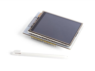
 Here's how to make the Velleman 2.5" tft work with Arduino Leonardo: I got a bit of a headache learning the basics to connect my Arduino to my new tft, I bought this to teach myself about simple app programming with Arduino but quickly learned about the limitations and actual functionality of this setup. I bought the Velleman 2.5" tft uno/mega shield(VMA412) this was tricky to figure out but simple to set up and use. The first thing to realize before you make any big ideas for this display, the size of the libraries for the touchscreen and graphics are very large compared to the memory on an Arduino, and it's even worse for a Leonardo because more of the memory is used up to save money on the design. This gave me my first problem, while trying to upload the calibration program I kept getting this error; "Sketch too big;" The dialogue suggests removing code to save space. Next just quickly go through the code and look for any redundant print statements, any print statement that didn't seem functional or important just get deleted and this will save enough space to run the test program. 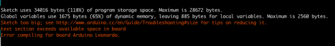 The numbers you really want to keep from the screen test are XP, YP, XM, YM. You can get these values by using the program file TouchScreen_Calibr_native.ino for "MCUFRIEND UNO" Display Shields which the Vellemans datasheet describes it as. Their datasheet doesn't cover a way to modify the display to use the leftover COM1 connection but they do say that this connection is for programming purposes and not for regular use. I was trying to figure out a way to reduce the number of pins I'm using while the screen is still fully functional. I've been trying to figure out if I could use a shift register to reduce the amount of pins needed or to just not connect the built in SD card but for now it works just by bending he unneeded pins out of the way and connecting a wire to them. The best way to get more functionality is to get an Arduino mega which will have many pins leftover and a larger memory which would solve all the problems I had with this display.
0 Comments
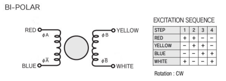
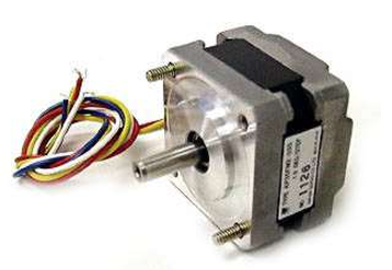 A while ago I purchased a couple of these KP35FM2-035 stepper motors from Sayal Electronics. I had a lot of trouble finding the datasheet or any relevant info. After searching the web and asking one of my professors I figured out how to find the values I was looking for. I hope this is useful to you too! Some of these values can be used to create the other given values. Please scroll down to find datasheet info. To find the number of steps from step angle: All you need to do Is divide a full circle (360 degrees) by the number of steps or by the step angle to change between the two values. 360 (degrees) / 1.8 (step angle) = 200 (number of steps) 360 (degrees) / 200 (number of steps) = 1.8 (step angle) ____________________________________________________ To find voltage, current or resistance use Ohm's Law: V=Volts, I=Amps(Current), R=Resistance V=IR or I=V/R or R=V/I The easiest value to find first Is the Resistance because you can measure It with a multimeter without powering the circuit. R = 37 Ohms Next, make an educated guess at what voltage or current you want to use or have available. Some good examples include the standard voltages: 3.3V, 5V, 9V, 12V, 24V Some examples of currents: 50mA = 0.05 A , 500mA = 0.5A The average current of one LED: 10 - 30 mA The maximum current of one Arduino pin: 40 - 50 mA 40 mA is the maximum current that you can run through the I/O pins of the Arduino Uno. Any more and you will damage the chip or some other part of the circuit. This means that we can't supply the current from the Arduino directly because the motor can draw up to 600mA. It is still possible to power the stepper from the Arduino at a lower current but this will lower the torque as well. I'll start by guessing a voltage, the one I guessed first was 12V so that is what I will use for this example: 12V / 37 Ohms = 0.32 A This value Is lower than the stepper motors rated current. 24V / 37 Ohms = 0.65 A In this case there is a 24V supply which then exceeds the rated motor current. At both voltages there would be damage to the Arduino. Components are needed to reduce the current so the motor and Arduino are protected. Another component Is needed to reverse the polarity of the motor coils and to help isolate the motors circuit from the Arduinos circuit. This component is called an H-bridge.
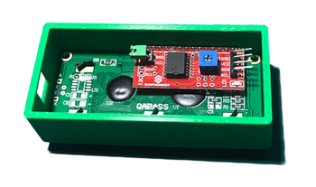 The 16x2 LCD on its own requires a ton of pins in order to work, so the I2C module (Red) is used to communicate between the Arduino and the LCD. With this component the difficulty was in finding the right Arduino Library to include at the top of the sketch, if the desktop app library explorer doesn't have the right library available then you can use the download link I will include here. The library is called "LiquidCrystal" and the tutorial I followed is available here: https://www.makerguides.com/character-i2c-lcd-arduino-tutorial/ Download link: https://www.makerguides.com/wp-content/uploads/2019/02/LiquidCrystal_I2C-master.zip |
 RSS Feed
